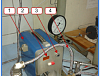
A laboratory experimental set-upTEP-1 (experimental, pulsating heat exchanger) consists of two practically identical “tube-in-tube” heat exchangers. Their difference lies only in the fact that one of the heat exchangers has partial by-passes of the channel cross section spaced from at each other at the same distance. A pulsating facility is able to generate harmonic flow oscillations of a heat exchanger in the heat exchanger system over the frequency range from 0 to 3 Hz. The heat exchanger oscillation amplitude can also be controlled by directing some flow to by-pass pulsating device.
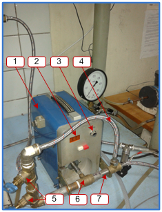
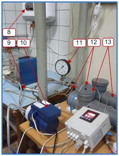
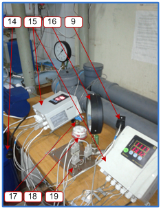
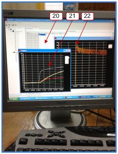
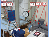
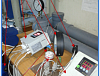
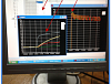
1 – pulsating device; 2 – frequency indicator; 3 – frequency control; 4 – by-pass circuit of the pulsating device; 5 – amplitude control; 6 – ball pulsator; 7 – direct circuit of the pulsating device; 8 – thermostat; 9 – pressure sensors; 10 – pump-compressor; 11 – pump-compressor gauge; 12 – thermoelectric converters; 13 – heat exchangers; 14 – receiver; 15 – measuring transducers “Sosna”; 16 – control gauge; 17 – flow rate control; 18 – flow rate meter; 19 – switch board; 20 – measurement control program window; 21 – temperature window; 22 – pressure window
+375(17)350-21-36

A.V. LUIKOV HEAT AND MASS TRANSFER INSTITUTE
OF THE NATIONAL ACADEMY OF SCIENCES OF BELARUS